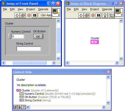
Cluster data type
A cluster is a LabVIEW data type that groups data elements of mixed types. A cluster is similar to a record or a struct in text-based programming languages. Clusters can be stored solitarely in a ctl.
Bundling several data elements into clusters eliminates wire clutter on the block diagram and reduces the number of connector pane terminals that subVIs need. The connector pane has, at most, 28 terminals. If a front panel contains more than 28 controls and indicators that you want to use programmatically, you can group some of them into a cluster and assign the cluster to a terminal on the connector pane. Like an array, a cluster is either a control or an indicator. A cluster cannot contain a mixture of controls and indicators.
Types of Clusters
There are three types of clusters which are signified on the Block Diagram as different colors.
 A brown cluster is a Numeric Cluster data type and consists of numeric data types. Numerical actions such as 'plus', 'minus' and others can be applied to the cluster directly. Additionally the size of the cluster (bytewise) is fixed.
 A pink cluster is a Common Cluster data type and has a variable size because of the use of mixed data types which can include, (for instance), strings or arrays.
 A gold/yellow cluster is used to signify an Error Cluster data type (LabVIEW 8.20 and later; before LabVIEW 8.20 Error clusters were also pink).
Creating Cluster Controls and Indicators
To create a cluster control or indicator, select a cluster on the Controls>>All Controls>>Array & Cluster palette, place it on the front panel, and drag controls or indicators into the cluster shell. Resize the cluster shell by dragging the cursor while you place the cluster shell.

Creating Cluster Constants
Create a cluster constant on the block diagram by selecting a cluster constant on the Cluster palette, placing it on the block diagram, and dragging a constant into the cluster shell.
If you have a cluster control or indicator on the front panel and you want to create a cluster constant containing the same elements on the block diagram, you can either drag that cluster from the front panel to the block diagram or right-click the cluster on the front panel and select Create>>Constant from the shortcut menu.
Cluster Order
Cluster elements have a logical order unrelated to their position in the shell. The first object you place in the cluster is element 0, the second is element 1, and so on. If you delete an element, the order adjusts automatically.
The cluster order determines the order in which the elements appear as terminals on the Bundle and Unbundle functions on the block diagram.
You can view and modify the cluster order by right-clicking the cluster border and selecting Reorder Controls In Cluster from the shortcut menu.
The white box on each element shows its current place in the cluster order. The black box shows the new place in the order for an element. To set the order of a cluster element, type the new order number in the Click to set to text box and click the element. The cluster order of the element changes, and the cluster order of other elements adjusts. Save the changes by clicking the Confirm button on the toolbar. Revert to the original order by clicking the Cancel button.
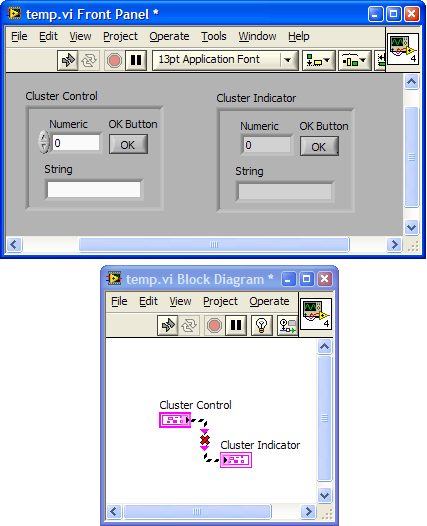
Corresponding elements, determined by the cluster order, must have compatible data types. For example, in one cluster, element 0 is a numeric control, and element 1 is a string control. In a second cluster, element 0 is a numeric indicator, and element 1 is a string indicator. The cluster control correctly wires to the cluster indicator.
However, if you change the cluster order of the indicator so the string is element 00, and the numeric is element 11, the wire from the cluster control to the cluster indicator appears broken, indicating that the data types do not match.

