| VI Server Property Information
|
| Property ID
|
78CA7010
|
| Scope
|
VI Scripting
|
| Data Name
|
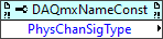
PhysChanSigType
|
| Short Name*
|
PhysChanSigType
|
| Long Name*
|
Physical Channel:Signal Type
|
| * Displayed here in English. Short and Long names appear in the language of the LabVIEW IDE.
|
| Owning Class ID
|
16457
|
| Owning Class Name
|
DAQmxNameConstant Class
|
| Data Type
|
I32 data type

|
| Property Node
|
|
| Available in Real-Time Operating System | Yes |
| Available in Run-Time Engine | Yes |
| Loads the block diagram into memory | No |
| Loads the front panel into memory | No |
| Need to authenticate before use | No |
| Permissions | Read/Write |
| Remote access allowed | Yes |
| Settable when the VI is running | Yes |
Indicates the type of signals that the control displays. Use this property only if the control is a DAQmx Physical Channel control.
If the control is set to physical channel, indicates the type of signals that the control will display. 1 - AI, 2 - AO, 4 - DI, 8 - DO, 16 - CI, 32 - CO, 64 - Switch, 128 - Internal. In order to have the control display multiple signal types, add the desired numbers together. In other words, for AI and CO to be displayed, pass 33 (32 + 1) into the node.
| 1
|
AI
|
| 2
|
AO
|
| 4
|
DI
|
| 8
|
DO
|
| 16
|
CI
|
| 32
|
C0
|
| 64
|
Switch
|
| 128
|
Internal
|
To have the control display multiple signal types, add the appropriate numbers together. For example, to display AI and CO, pass 33 (32 + 1) into the node.
Uses
History
| Version
|
Change(s)
|

|
More info to come.
|
See Also
External Links