Conditional Disable structure
| Object information | |
|---|---|
| Owning palette(s) | Structures palette |
| Type | VI |
| Requires | Basic Development Environment |
| Icon | |

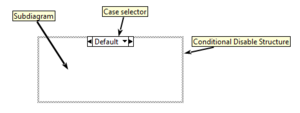
The Conditional Disable Structure is a primitive structure that can have one or more subdiagrams (also known as "Cases"), one of which is executed at runtime. The subdiagram to execute is determined based on conditions in the project that are evaluated at compile-time.
Symbols
Symbols are unique identifiers that have case-sensitive values of alpha-numeric characters and underscores ([A-Za-z0-9_]+). Symbols are defined in multiple ways:
| Environment | LabVIEW always provides the environment symbols RUN_TIME_ENGINE, TARGET_TYPE and TARGET_BITNESS by default. |
|---|---|
| Project | If a VI is located inside a project, the additional symbols CPU and OS are available by default. |
| FPGA | If the FPGA module is installed, the additional symbols FPGA_EXECUTION_MODE, FPGA_TARGET_FAMILY and FPGA_TARGET_CLASS are made available. |
| Custom (project) | Additional symbols can be added via the project properties. |
Environment and project symbols are managed by LabVIEW and cannot be changed. Custom symbols can be added manually.
Environment symbols
These symbols are defined by LabVIEW and cannot be changed.
RUN_TIME_ENGINE
Determines if the subdiagram is executed in the Run-Time Engine.
| Value | Description |
|---|---|
| True | Executes in the Run-Time Engine. |
| False | Executes in the Development Environment. |
TARGET_TYPE
Determines on which platforms or targets the subdiagram executes.
| Value | Description |
|---|---|
| Windows | Executes on a Windows target. |
| FPGA | Executes on an FPGA target. |
| IPBuilder | Executes on IPBuilder FPGA targets. |
| Embedded | Executes on an Embedded target. |
| RT | Executes on an Real-Time target. |
| Mac | Executes on a Mac target. |
| Unix | Executes on a Unix target. |
| PocketPC | Executes on a PocketPC target. |
| DSP | Executes on a DSP target. |
TARGET_BITNESS
Determines the bitness of the platform to execute the subdiagram.
| Value | Description |
|---|---|
| 32 | Executes on a 32-bit platform. |
| 64 | Executes on a 64-bit platform. |
Project symbols
These symbols are only available for VIs inside projects.
CPU
Determines the CPU on which the subdiagram executes.
| Value | Description | ||
|---|---|---|---|
| PowerPC | Executes on PowerPC CPUs. | ||
| x86 | Executes on x86 CPUs. | ||
| ARM | Executes on ARM CPUs. | ||
| null |
|
OS
Determines the type of Operating System.
| Value | Description |
|---|---|
| Linux | Executes on Linux. |
| Mac | Executes on Mac. |
| PharLap | Executes on PharLap. |
| VxWorks | Executs on VxWorks. |
| Win | Executes on Windows. |
| null |
FPGA symbols
These symbols are defined by the LabVIEW FPGA module and cannot be changed. Symbols are available if the VI is placed under an FPGA target in the project.
FPGA_EXECUTION_MODE
Determines the execution mode of the subdiagram within an FPGA VI.
| Value | Description |
|---|---|
| FPGA_TARGET | Executes on an FPGA target. |
| DEV_COMPUTER_SIM_IO | Executes in a Simulated I/O simulation environment. |
| DEV_COMPUTER_REAL_IO | Executes in a Real I/O simulation environment. |
| THIRD_PARTY_SIMULATION | Executes in a Third-Party simulation environment. |
FPGA_TARGET_FAMILY
Determines the FPGA family.
| Value | Description |
|---|---|
| VIRTEX2 | Executes on the VIRTEX2 family. |
| VIRTEX5 | Executes on the VIRTEX5 family. |
| VIRTEX6 | Executes on the VIRTEX6 family. |
| SPARTAN3 | Executes on the SPARTAN3 family. |
| SPARTAN6 | Executes on the SPARTAN6 family. |
| ZYNQ | Executes on the ZYNQ family. |
| KINTEX7 | Executes on the KINTEX7 family. |
FPGA_TARGET_CLASS
Determines the FPGA class. Available values depend on the connected FPGA target and can be accessed from the FPGA Target Properties dialog box.
Conditions
The Diagram Disable structure supports two conditions:
| == | The value of the symbol must be equal to the specified value. |
|---|---|
| != | The value of the symbol must be different (not equal) to the specified value. |
Each subdiagram can have one or more conditions.
Configure conditions

Conditions are defined in the Configure Condition dialog box. This dialog box appears for any of the following right-click menu options.
| Add Subdiagram After... | Adds a subdiagram after the current diagram. |
|---|---|
| Add Subdiagram Before... | Adds a subdiagram before the current diagram. |
| Duplicate Subdiagram | Duplicates the current subdiagram. |
| Edit Condition For This Subdiagram... | Opens the Configure Condition dialog box for the current subdiagram. |
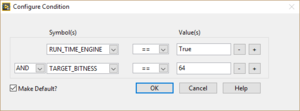
All available symbols are listed in the drop-down list under Symbol(s). A new symbol can be defined by manually writing the symbol name in the drop-down list. However, the symbol will not appear in the project automatically. The next drop-down list after Symbol(s) defines the condition for the value.
The buttons "+" and "-" add or remove additional conditions. If more than one condition is defined, a new drop-down list appears on the left which defines how the results of conditions are evaluated. Available options are: AND and OR.
The checkbox "Make Default?" makes the current subdiagram the default diagram if none of the conditions for any subdiagram was met.
Custom conditional disable symbols

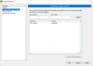
Conditional disable symbols can be defined in the project properties on the Conditional Disable Symbols page. To define a new symbol, insert the symbol name and it's initial value and press "Add". The selected symbol can be removed with the "Remove Selected Items" button.
The value of a symbol can be changed by clicking in the "Values" field in the list and writing the new value.
Best practice
- Use the Diagram Disable structure to permanently or temporarily disable sections of code.
- Use the upper case naming convention for symbol names.
- Use the upper case naming convention for symbol values.
History
| |
Which version added the RUN_TIME_ENGINE symbol? |
| |
When and how are the FPGA_* symbols added? |
| |
Which version added the IPBuilder and DSP values for the TARGET_TYPE symbol? |
| |
Can anyone confirm that the value Linux for TARGET_TYPE was renamed to Unix between LV8.6 and LV2009? |
| Version | Change(s) |
|---|---|

|
Objects in the inactive subdiagrams are no longer loaded into memory. |

|
The Conditional Disable structure was added. |
