Connector pane
The Connector Pane is used to pass data to and from a SubVI. The Connector Pane is available in the Front Panel window's upper right corner next to the VI Icon.
Patterns
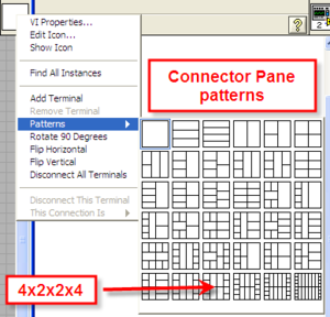
Right-click on the Connector Pane to choose a pattern.

It is considered good practice to choose a pattern that has more inputs/outputs than you need when writing the VI so that new inputs or outputs can be added without changing the connector pane and causing the VI's that link to your subVI to recompile. The 4x2x2x4 pattern highlighted above is the most commonly used for NI primitives. In LabVIEW 8 and above the connector pane is defaulted to the 4x2x2x4 pattern. To customize the default connector pane used for new VIs, set the defaultConPane variable in your LabVIEW configuration file (see Miscellaneous>defaultConPane).

Increase/Decrease Terminals
Right-clicking the Connector Pane and selecting Add Terminal or Remove Terminal effectively moves the pattern up or down one.
Changing Orientation
Right-clicking the Connector Pane and selecting Rotate 90 Degrees, Flip Horizontal, or Flip Vertical keeps the same pattern but changes the orientation.
Connecting Controls and Indicators
To connect a control or an indicator to a terminal on the Connector Pane:
- Select the control or indicator
- Click on the desired terminal on the Connector Pane
Switching Terminal Positions
To switch or move a control or indicator to a different terminal:
- Click on the terminal to move on the Connector Pane
- Hold-down Ctrl and click on a different terminal. This will switch the two terminals, whether connected to something or empty.
Disconnecting a Terminal
Right-click on the Connector Pane and select either:
- Disconnect All Terminals - to disconnect all terminals
- Disconnet This Terminal - to disconnect just the terminal that was clicked on
Requirement Level
Right-clicking a terminal and selection This Connection Is presents four different options. The terminals can be set to:
- Required - sets the input as required. If the input is not wired, the program will not run, see Broken Run Arrow.
- Recommended - sets the input as recommended. If the input is not wired, the program will still run and the default value for control is used.
- Optional - sets the input as optional which is the same as recommended but the terminal will not appear in the Context Help.
- Dynamic Dispatch Input (Required) or Dynamic Dispatch Output (Recommended) - Greyed out except for class inputs and outputs. Sets the VI as Dynamic dispatch.
Index of Terminals
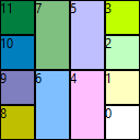
When using VI Scripting to access a Connector Pane (for example: ConnectorPane class/Controls[] property), the terminals by defaultare ordered from Right to Left, Bottom to Top. This changes if the pattern is rotated or flipped. Therefore, for a standard 4x2x2x4 pattern the terminals are indexed as follows:
To see other patterns, see Connector Pane Patterns.
Best Practices
Terminal Organization
- Use the 4x2x2x4 pattern even if it leaves empty spaces. Only go to patterns with more terminals if necessary. However, before switching to more terminals, consider bundling inputs or outputs into Clusters.
- Put inputs on the left side of the Connector Pane and outputs on the right.
- Use the bottom corners for error in and error out.
- If the VI is a method in a class, use the top corners as the class object input and output.
Require by Default
- Turn the flag in the Options dialog on which will require all inputs by default, except the error in. This makes it so inputs to SubVIs don't get accidentally forgotten.
History
| Version | Change(s) |
|---|---|

|
In LabVIEW 2011 the Connector Pane was changed to always be visible on the Front Panel window next to the VI Icon. LabVIEW 2010 and earlier only the Connector Pane or the VI Icon was visible at a time and they were toggled between via a right-click menu (Show Connector or Show Icon).
Also, previously to LabVIEW 2011, when creating a SubVI from a selection, the SubVI would be created with a varying pattern with just the number of inputs or outputs needed. In LabVIEW 2011 and later, the new SubVI will default to the 4x2x2x4 pattern, if the input/output count fits, and the errors will default to the bottom corners. |

