Block Diagram
 |
This page is under construction. This page or section is currently in the middle of an expansion or major revamping. However, you are welcome to assist in its construction by editing it as well. Please view the edit history should you wish to contact the person who placed this template. If this article has not been edited in several days please remove this template. Please don't delete this page unless the page hasn't been edited in several days. While actively editing, consider adding {{inuse}} to reduce edit conflicts. |
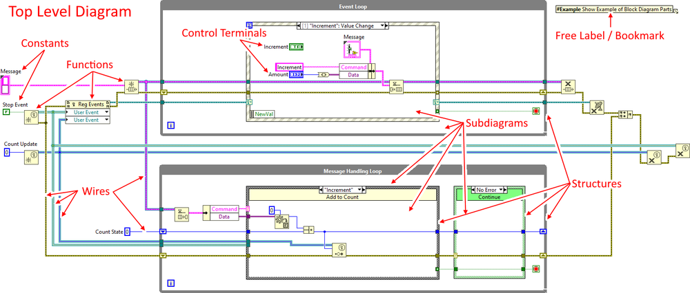
The Block Diagram is the part of a VI that contains the graphical source code known as G. Front Panel controls and indicators appear on the Block Diagram as control terminals. The control terminals for the Front Panel controls are the input where the Front Panel indicators are the output. Wires connect the terminals to other Nodes and each other to flow the data between them similar to a flow chart (see Dataflow). Operational order is dictated by Dataflow. Parts that are not connected are automatically parallelized by the compiler to take advantage of parallel processing that is available in modern multi-core computers.
Parts of a Block Diagram

- Top Level Diagram
- Control Terminals
- Nodes
- Structures
- Sub-Diagrams
- Functions
- SubVIs
- Structures
- Constants
- Wires
- Decorations
- Free Labels
- Bookmarks
- Free Labels
Best Practices
Code Organization
- Organize code to flow from Left-to-Right, Top-to-Bottom. Keep all input control terminals on the left and all output control terminals on the right.
- Do not place control terminals inside of Case Structures.
Code Size
If possible keep all code on a Block Diagram viewable on the screen without scrolling. Use SubVIs, Design patterns, etc. to organizes and enable code reuse. If necessary to scroll, only scroll in one direction, either Left and Right OR Up and Down.
Documentation
- When providing in-code documentation, document the Why's rather than the What's. If code is written well, what the code does should be easy to read. The documentation should help programmers viewing the code understand the original programmers reasoning and intent.
- Add documentation at the appropriate level. Documentation can be added to the VIs, Nodes, Wires, Subdiagrams, Constants and as Free Labels on the Block Diagram.
Design Patterns
Use commonly used Design patterns to standardize code organization among programmers.
